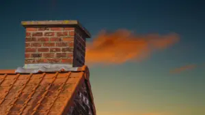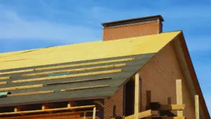
A well-designed roof does far more than protect a building from rain and sunlight; it defines strength, durability, and long-term performance. At the heart of many residential and commercial buildings is the Wood Roof Structure, a time-tested system valued for its strength, flexibility, and aesthetic appeal. From traditional homes to modern construction projects, wood remains one of the most reliable roofing materials available today.
Timber roof construction dates back thousands of years, long before steel and concrete became common. Ancient civilizations relied on timber roof framing for its availability and structural reliability. Even with modern alternatives available, wood continues to play a vital role in roofing systems across the world.
Understanding how a wood roof structure works is essential for homeowners planning renovations, builders managing construction projects, and DIY enthusiasts tackling repairs. This guide explains the fundamentals of wood roof structures, explores different system types, outlines construction and maintenance best practices, and helps readers make informed decisions about design, cost, and longevity.
1. Understanding Wood Roof Structure Basics
A Wood Roof Structure refers to the interconnected system of wooden components that support roofing materials and transfer loads safely to the walls and foundation. Its primary functions include structural support, protection from weather elements, and contributing to the building’s visual character.
One major advantage of wood roof systems is versatility. Timber is easier to modify on-site than steel, making it ideal for custom designs and renovations. Compared to other materials, wood also offers better insulation properties and a lower environmental impact when sourced responsibly.
Common applications include residential homes, commercial buildings, agricultural structures, and historical restorations. Whether paired with asphalt shingles or metal roofing, timber roof framing remains a dependable structural solution.
2. Essential Components of Wood Roof Structure
A properly built wood roof relies on several interconnected elements:
-
Rafters – Sloped structural beams forming the main framework
-
Ridge board or ridge beam – Horizontal member at the roof apex
-
Trusses – Engineered triangular units used in many modern homes
-
Purlins – Horizontal supports distributing roof loads
-
Collar beams and ties – Bracing elements preventing roof spread
-
Ceiling joists – Support interior ceilings and resist outward thrust
-
Roof decking or sheathing – Plywood or OSB base for roofing materials
-
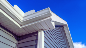
Fascia and soffits – Edge and underside finishing components
-
Struts and posts – Vertical supports transferring loads downward
Together, these components create a stable and efficient wooden roof truss and rafter system.
3. Types of Wood Roof Structure Systems
3.1 Rafter Roof Systems
Rafter roofs use individual roof rafters spaced evenly from the ridge to the wall plate. These systems are common in custom homes and renovations.
Pros:
-
Flexible design
-
Ideal for attic spaces
Cons:
-
Higher labor cost
-
Requires skilled carpentry
3.2 Truss Roof Systems
Prefabricated wooden roof trusses are widely used in modern construction.
Common types include:
-
King post trusses – Suitable for shorter spans
-
Queen post trusses – Ideal for 8–12 meter spans
-
Fink trusses – W-pattern design for residential homes
-
Scissor trusses – Allow vaulted ceilings
Truss systems reduce labor time, improve consistency, and often lower total project costs.
3.3 Purlin Roof Systems
Purlin systems use horizontal members to support rafters or decking, effectively distributing loads across the structure. These systems are common in larger buildings and rural construction.
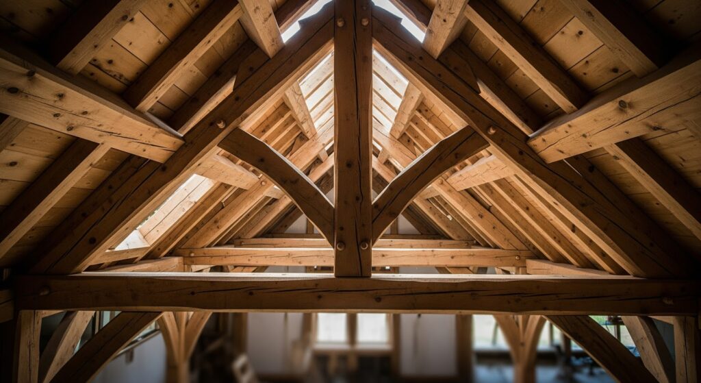
3.4 Timber Frame Roofs
Traditional timber framing features large exposed beams and classic joinery techniques. While visually striking, these systems require careful planning for insulation and utilities and often come at a higher cost.
3.5 Panelized Wood Roof Systems
Panelized systems are factory-built roof sections delivered ready for installation. They are commonly used in commercial projects for speed and quality control.
4. Wood Roof Structure Design Considerations
Designing a reliable Wood Roof Structure requires careful planning. Key considerations include:
-
Roof span and load requirements
-
Dead load, live load, snow load, and wind load calculations
-
Roof pitch and slope
-
Climate and environmental exposure
-
Local building codes and compliance
-
Material selection (solid lumber, engineered wood, grades)
Proper timber roof framing design ensures safety, performance, and longevity.
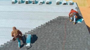
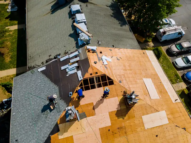
5. Construction & Installation Process
The construction process typically follows these steps:
-
Planning and structural design
-
Material selection and preparation
-
Layout and placement of rafters or trusses
-
Installation of roof decking
-
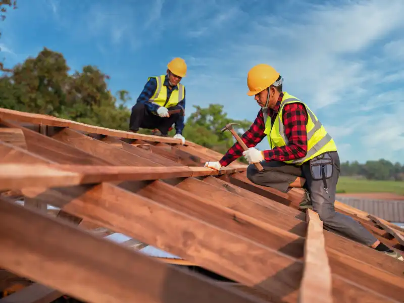
Bracing, fastening, and inspections
Common mistakes include improper spacing, inadequate bracing, and ignoring safety protocols. Using fall protection and following approved plans are essential for safe installation.

6. Maintenance & Longevity of Wood Roof Structure
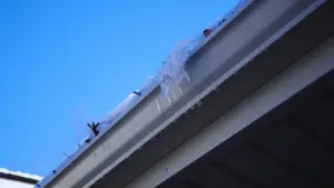
Regular inspections help extend the life of a Wood Roof Structure. Key maintenance tasks include:
-
Checking for moisture damage and rot
-
Inspecting for insect activity
-
Ensuring proper ventilation
-
Repairing leaks promptly
With proper care, most wooden roof truss and rafter systems can last 50 years or more. When structural damage is suspected, consulting a professional is strongly recommended.
7. Cost Factors & Budgeting
Costs vary depending on materials, labor, and roof complexity.
-
Truss systems are typically more affordable than site-built rafters
-
Skilled carpentry increases labor costs
-
Long-term value often outweighs initial savings
A well-built timber roof framing system offers excellent durability and return on investment.
8. Wood Roof Structure vs. Alternative Materials
Compared to steel trusses, wood offers easier modification, better insulation compatibility, and lower upfront costs. Hybrid systems combining wood and steel are sometimes used for large spans. Wood remains the preferred choice for most residential and light commercial projects.
Final Thought
A properly designed Wood Roof Structure is the foundation of a safe, durable, and efficient roof system. From understanding core components to selecting the right system and maintaining it over time, informed decisions make all the difference. Whether you are a homeowner planning a renovation or a builder managing a new project, professional design and quality construction are essential for long-term success. If you need expert guidance tailored to your specific project, contact us to discuss your roofing structure needs and ensure your roof is built to perform for decades.
Join Our Community
Join our community on Facebook, and don’t forget to subscribe to us on YouTube for new content each week.
FAQs
1. What is a wood roof structure?
A wood roof structure is a system of wooden components that support roofing materials and safely transfer loads to walls and foundations.
2. How long does a wood roof structure last?
With proper design and maintenance, a wood roof structure can last 50 years or more.
3. Are wood roof trusses better than rafters?
Trusses are cost-effective and fast to install, while rafters offer greater design flexibility and attic space.
4. What maintenance does a wood roof structure need?
Regular inspections for moisture, rot, insects, and ventilation issues help extend the roof’s lifespan.
5. Is a wood roof structure better than steel?
Wood is easier to customize, offers better insulation compatibility, and is more cost-effective for most residential projects.